Overview
In this project, I implemented various operations to manipulate meshes which allow people to represent 3-dimensional objects. Additionally, I also implemented a Binn-Phong shader and finished the system, based on the skeleton code that was given, to build Bezier curves and surfaces.
Section I: Bezier Curves and Surfaces
Part 1: Bezier curves with 1D de Casteljau subdivision
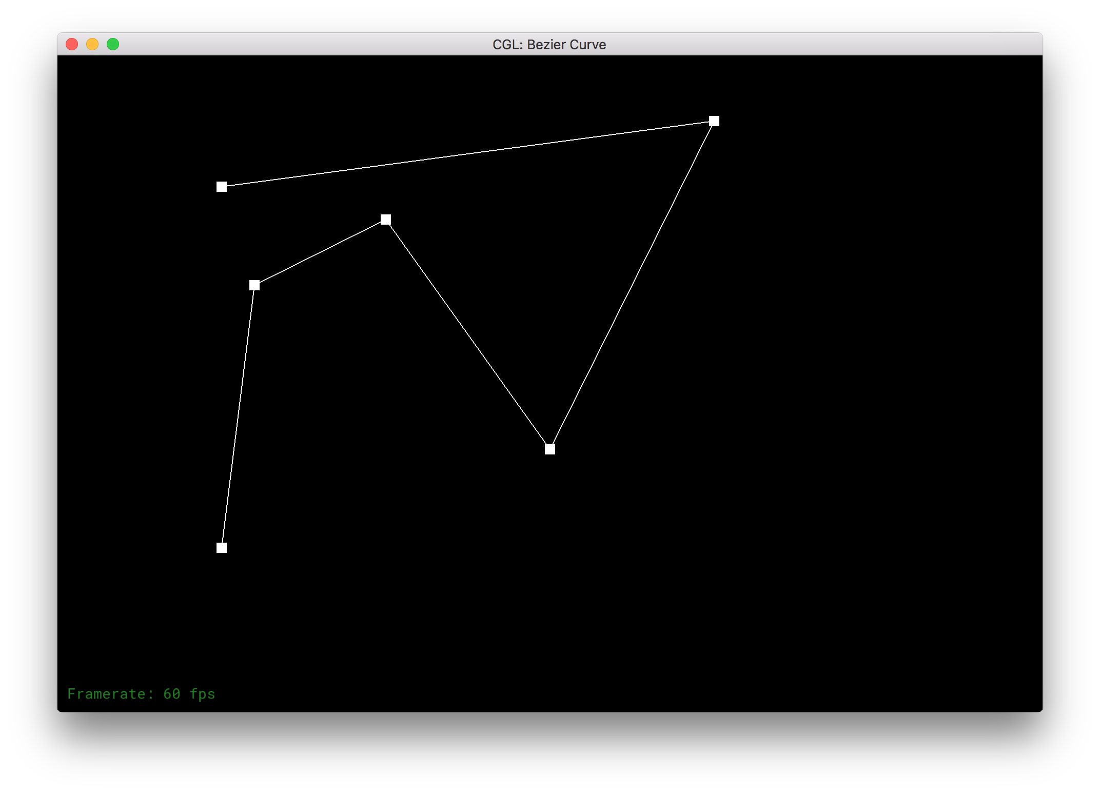
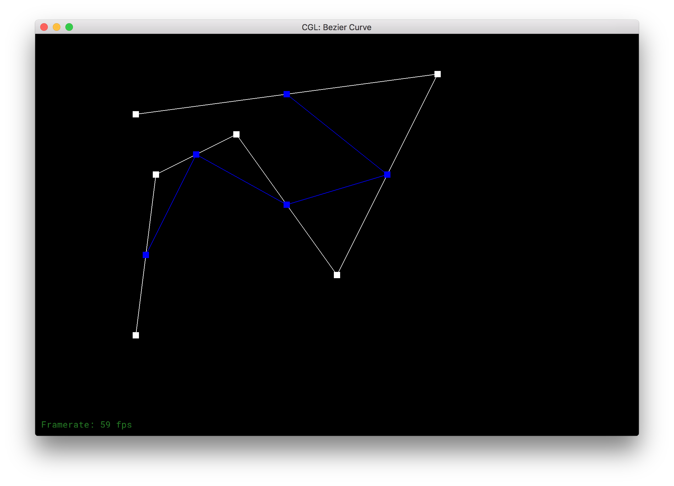
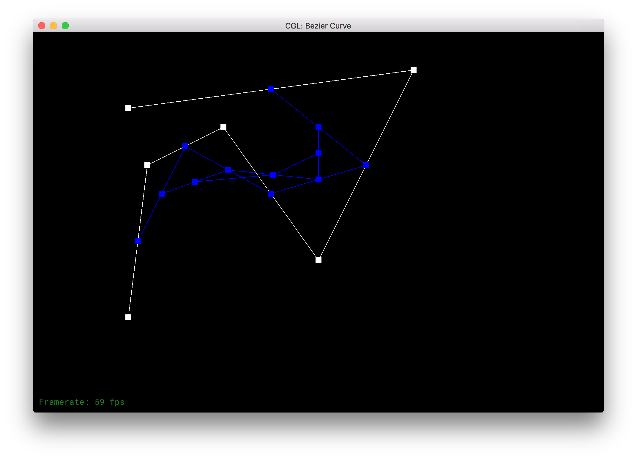
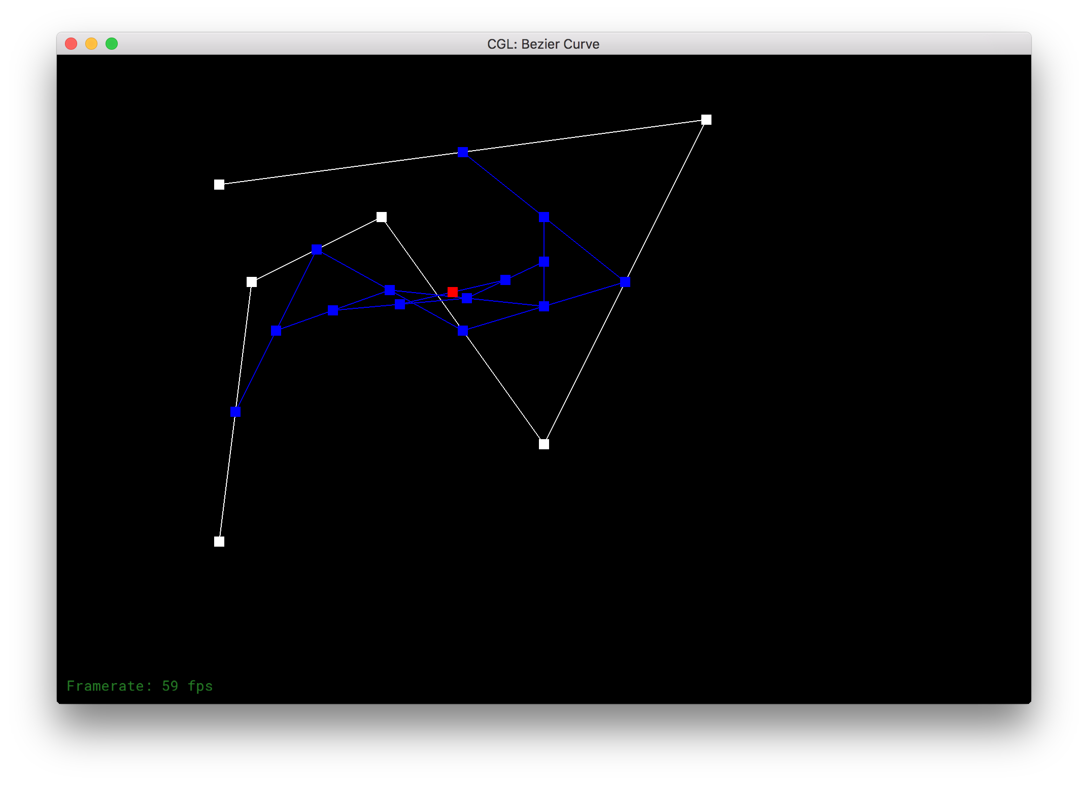
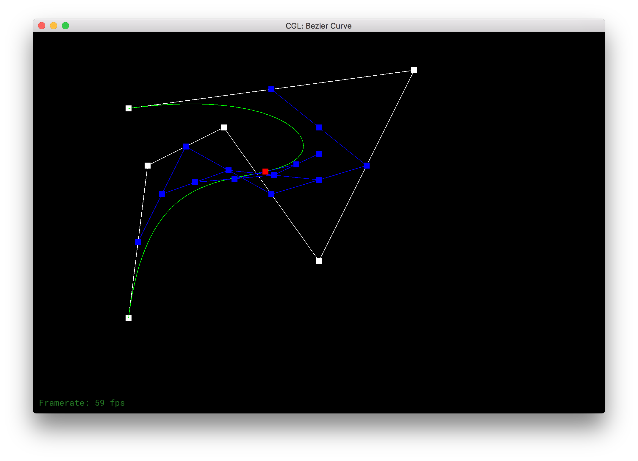
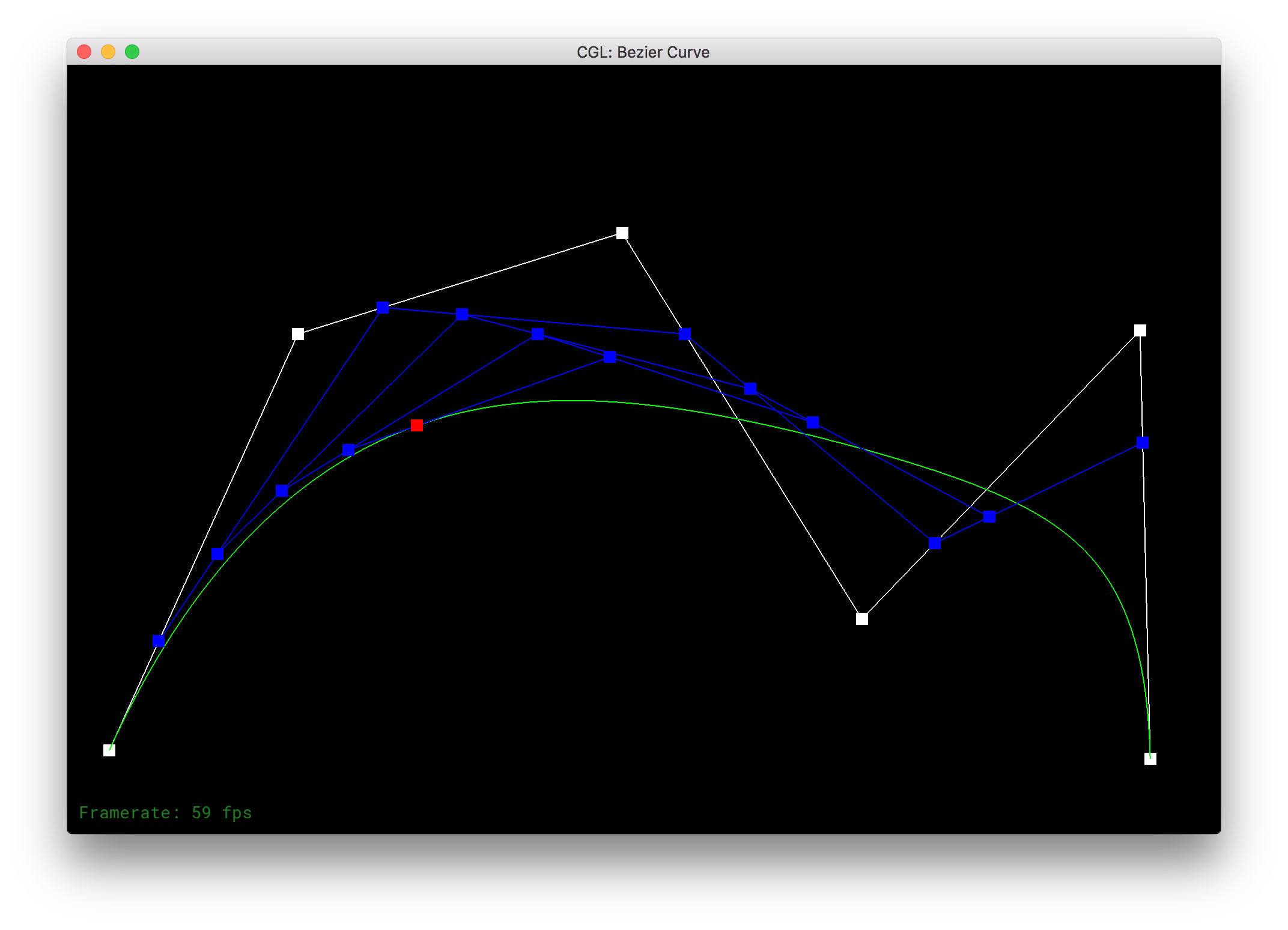
De Casteljau's algorithm involves the linear interpolation of the given points using a given input value t to determine the weighting of the interpolation and produce a final position. This algorithm can thus be used to create a smooth "Bezier" curve. In more detail: we begin by linearly interpolating the n given points pairwise to give us n - 1 new points. After that, we take the output points and interpolate those pairwise and we continue this until we are left with a single point.
Below is my result for a custom 6-point curve.
|
|

|
|

|
|
|
Additionally, the given GUI allows us to move the points around and change the given input value t to create a different curve.
|
Part 2: Bezier surfaces with separable 1D de Casteljau subdivision
Bezier curves can be applied to create Bezier surfaces simply by interpolating between the set of Bezier curves. Given a set of points for various Bezier curves, we first fully compute the interpolated curve for each set of points. After we have one point per curve, then we interpolate between these points until we get a final point that takes into account a second degree of movement. Doing so, we can represent surfaces in 2 dimensions given a position, (u, v).
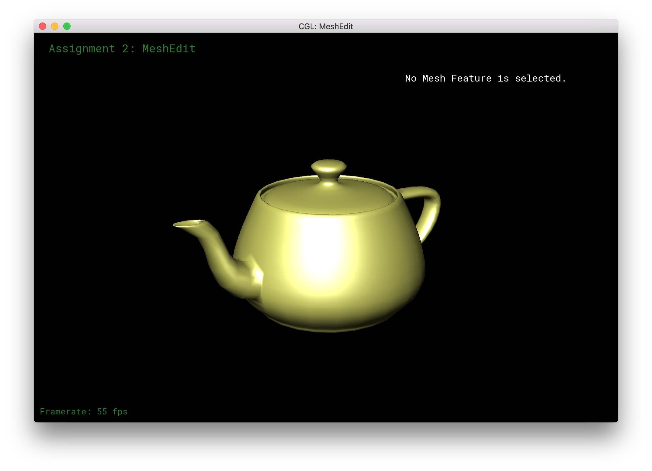
Below is an example of our Bezier surfaces at work in the form of a teapot:
|
Section II: Sampling
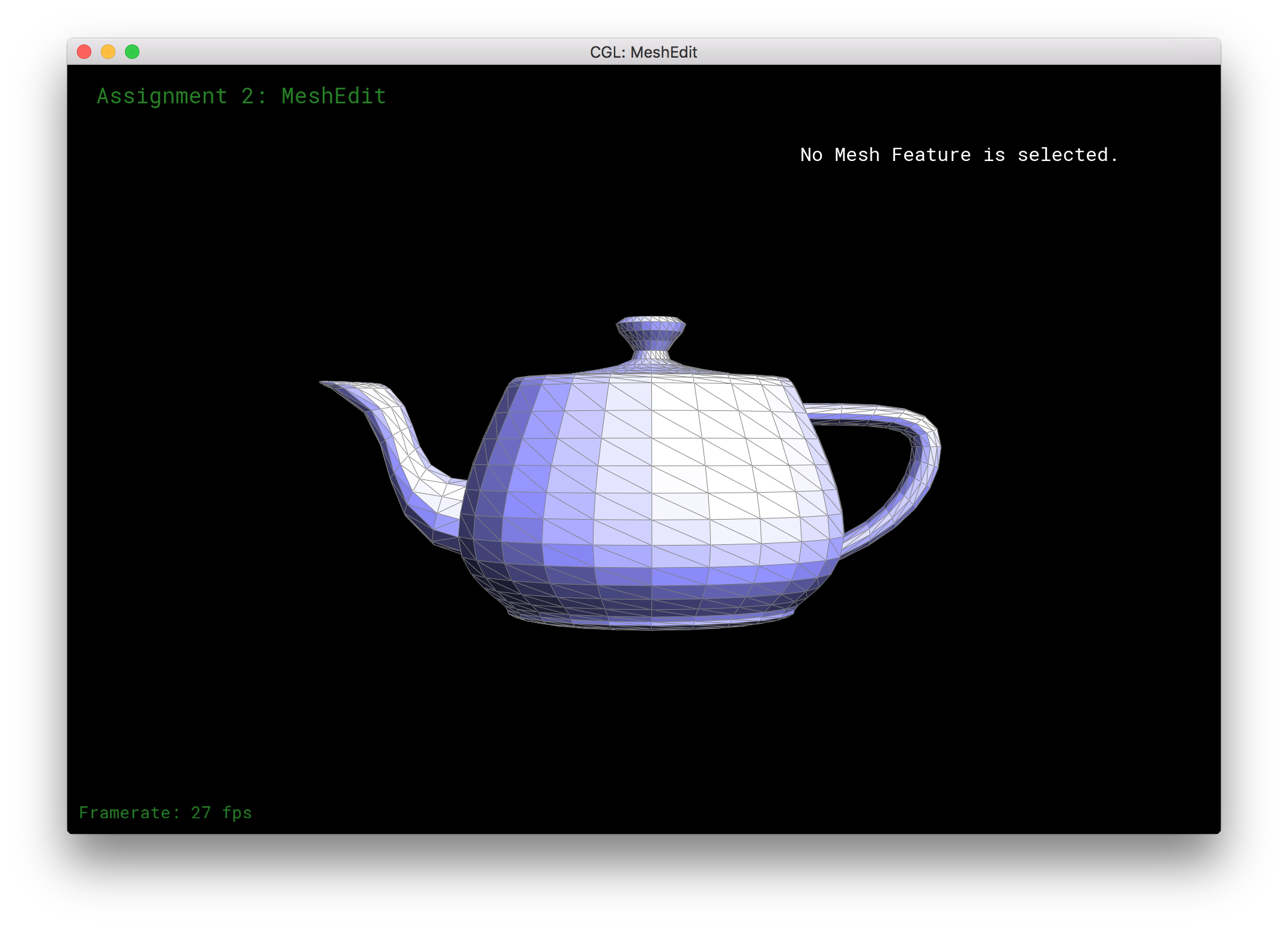
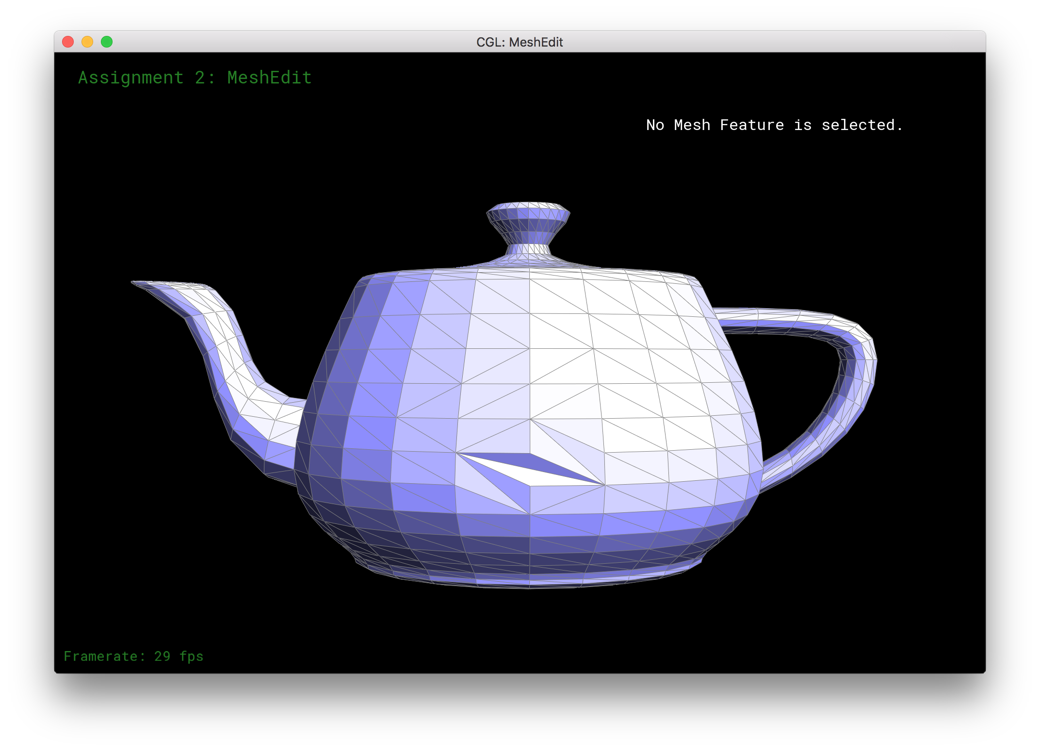
Part 3: Average normals for half-edge meshes
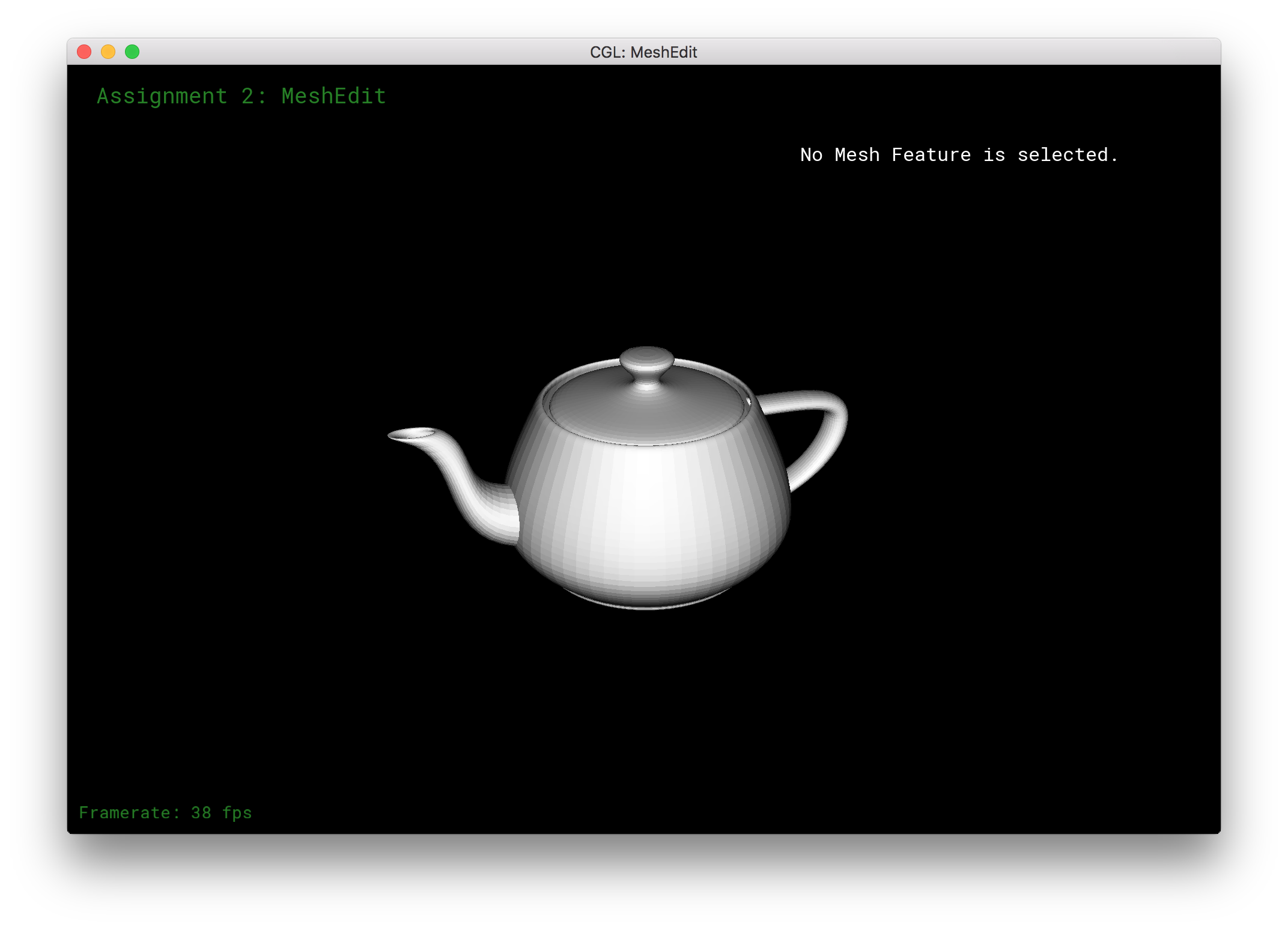
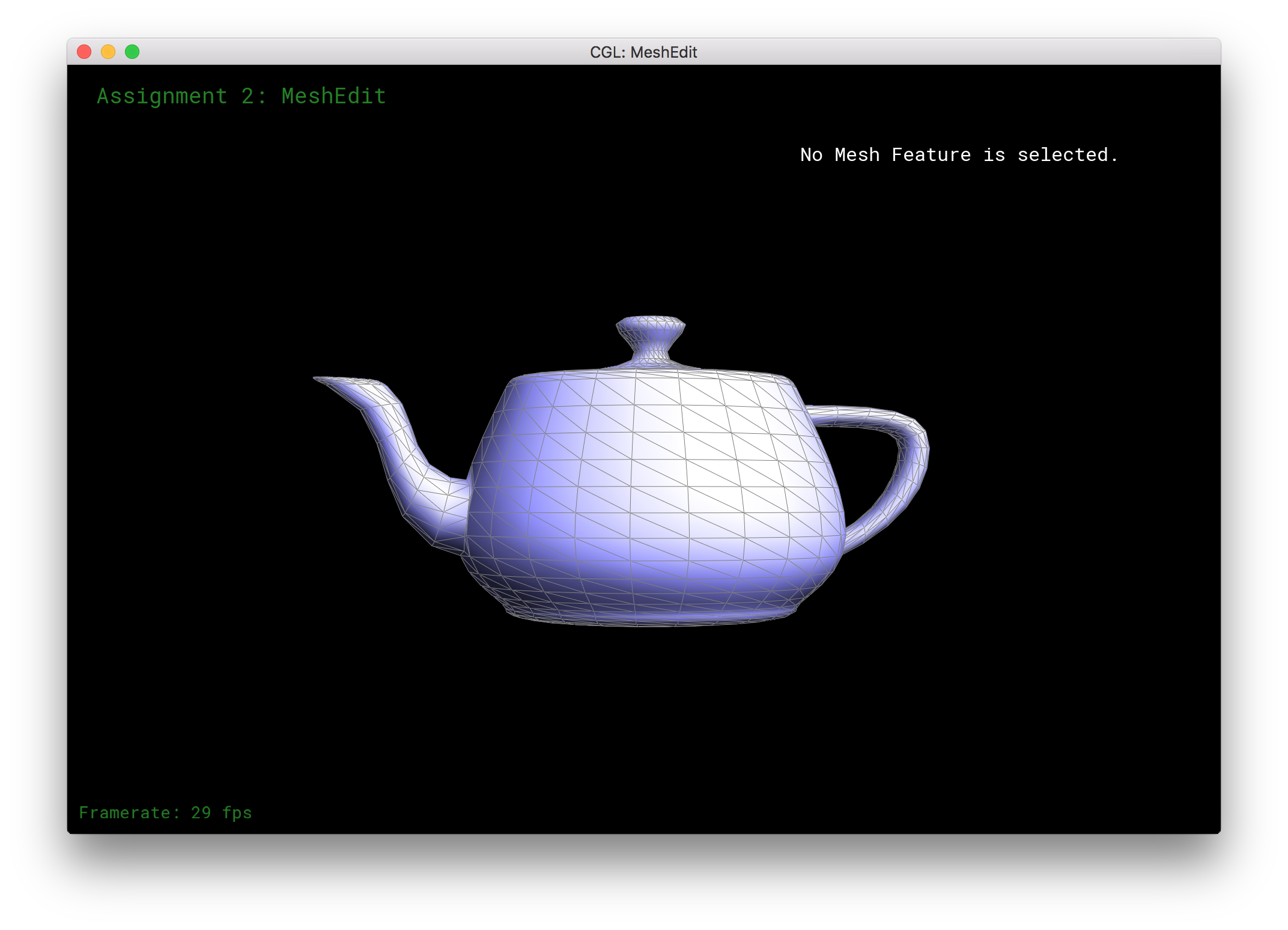
In this part of the project, we implemented average normals for half-edge meshes. The idea here is to smoothen a given mesh by averaging the magnitude and direction of a normal for a given vertex based off the areas of the neighboring faces. In order to get a metric for the area of a given face, we can take the cross product of two of the triangle's edges. We then sum these cross products, normalize, and use this vector as our new normal vector for a given vertex.
Doing so required knowledge of the half-edge mesh data structure but, all in all, was not too difficult to maneuver the mesh's edges. Below is a result showing the difference between using and not using average area normals to smoothen the teapot from the previous image.

|
|
Part 4: Half-edge flip
The half-edge flip operation consists of taking an edge between two vertices A and B and flipping it so that it becomes the connecting edge between two neighboring vertices C and D. In implementation, this requires us to modify the pointers in our half-edge mesh data structure. Every edge, face, vertex, and half-edge struct must be updated properly to reflect the changes that our flip operation causes in the geometry of the mesh.
In terms of debugging tactics, the best way to ensure that the flip operation did not malform the data structure is to check the operation by flipping many edges and by using the built-in check function mentioned in the project spec. Additionally, moving through the pointer assignments line by line while referencing an image of the mesh before and after the flip was very useful. Below is the same teapot as before but before and after some flip operations on the mesh.
|
|
Part 5: Half-edge split
The split operation is a little more involved than the flip operation. In this case, we take an edge and split it into two edges. This requires the creation of a new vertex, 3 new edges, 2 new faces, and 6 new halfedges (assuming that we re-use the already-existing parts of the mesh). Additionally, the new vertex's position is an average of the positions of the target edge's endpoints prior to splitting.
Below are some results before splitting edges, after splitting edges, and after flipping and splitting edges.
|
|

|

|
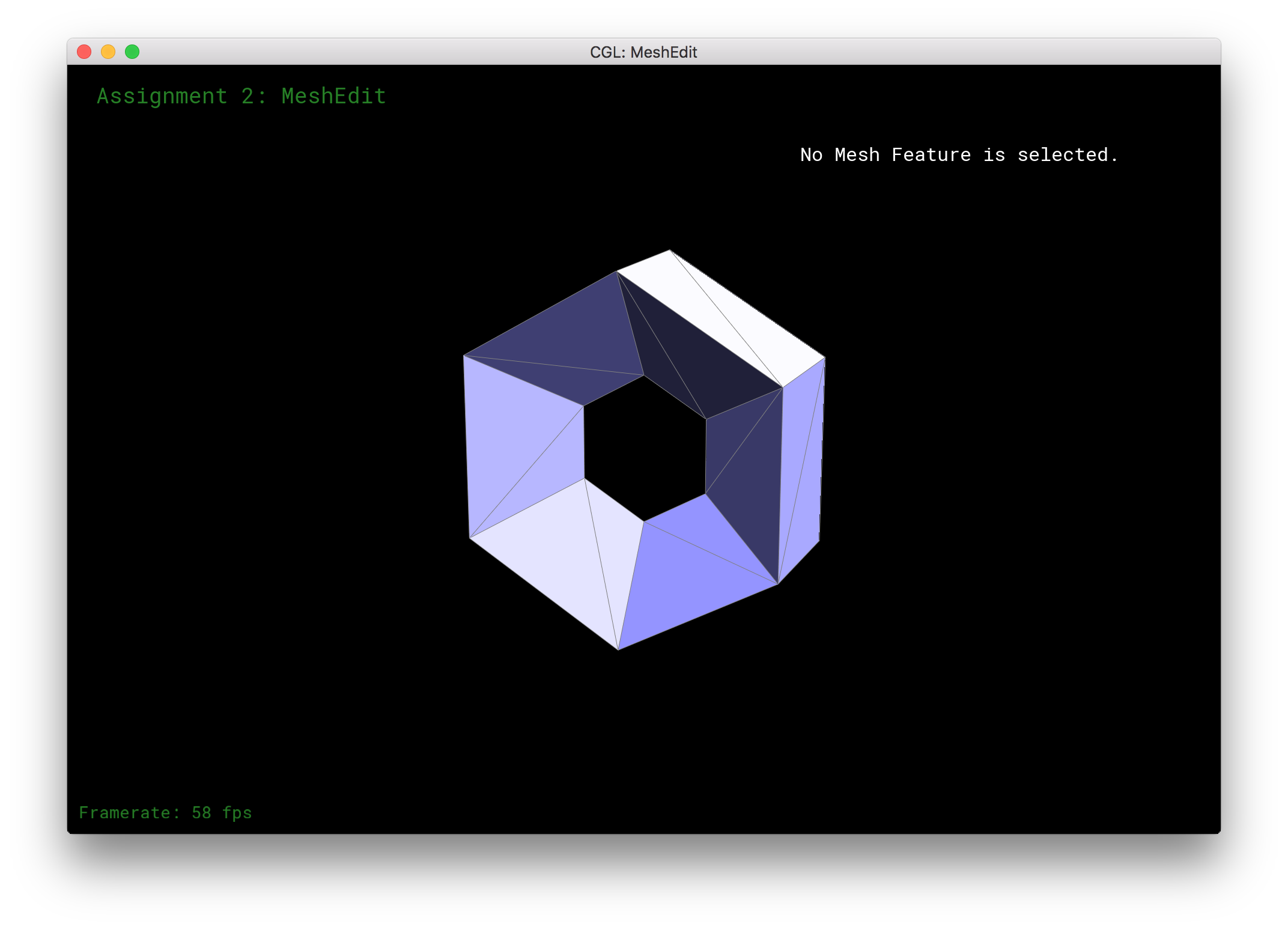
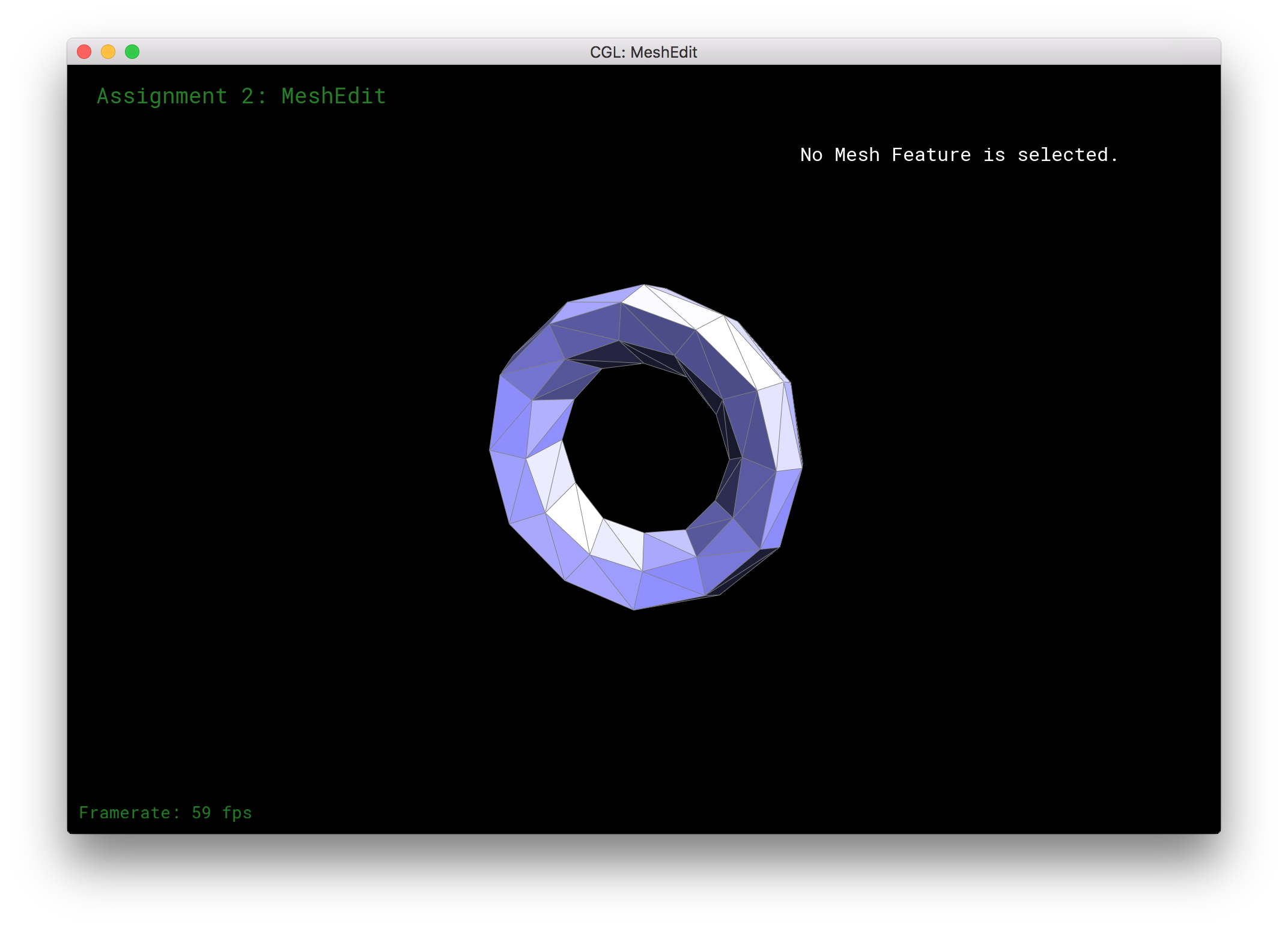
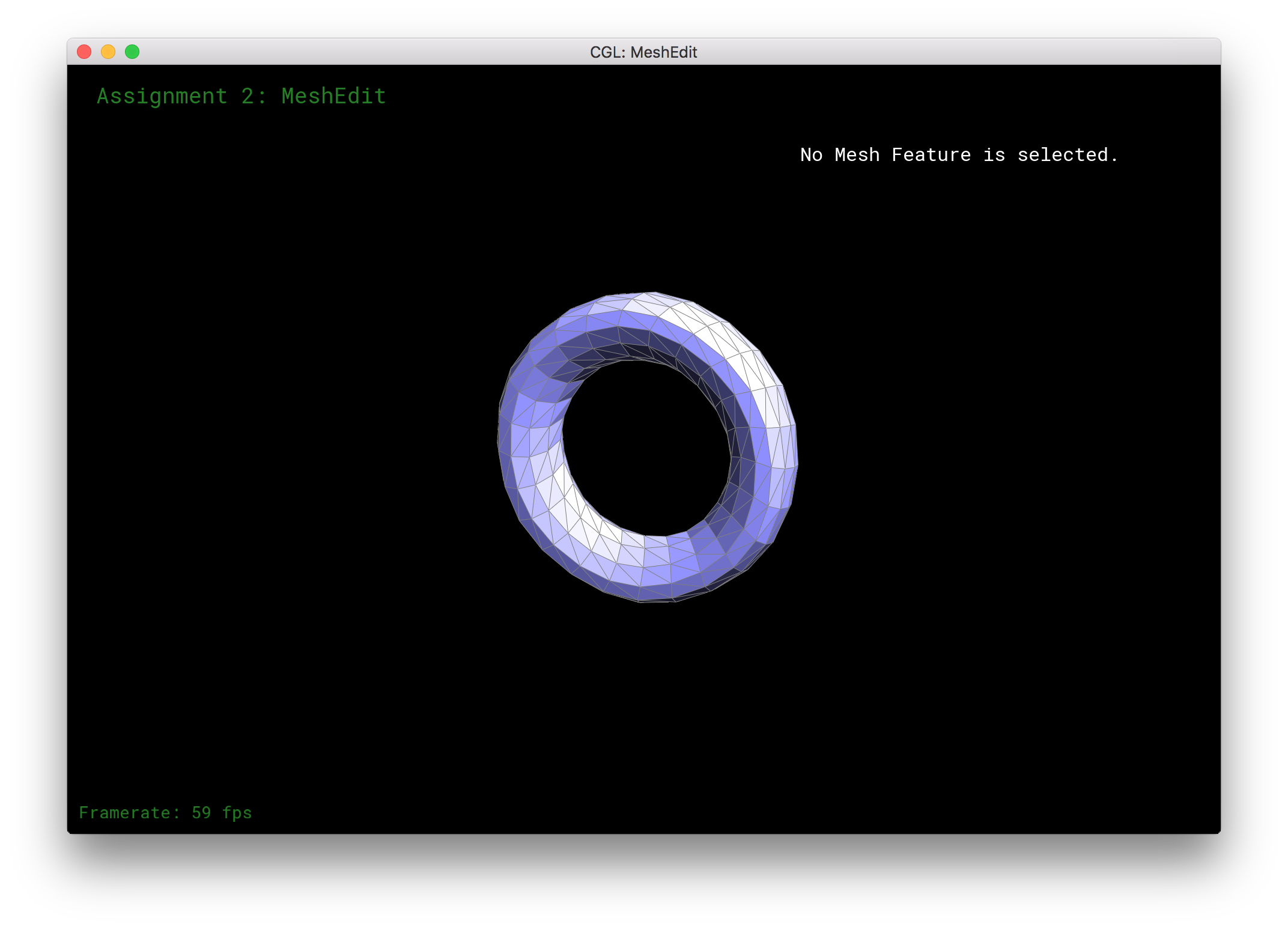
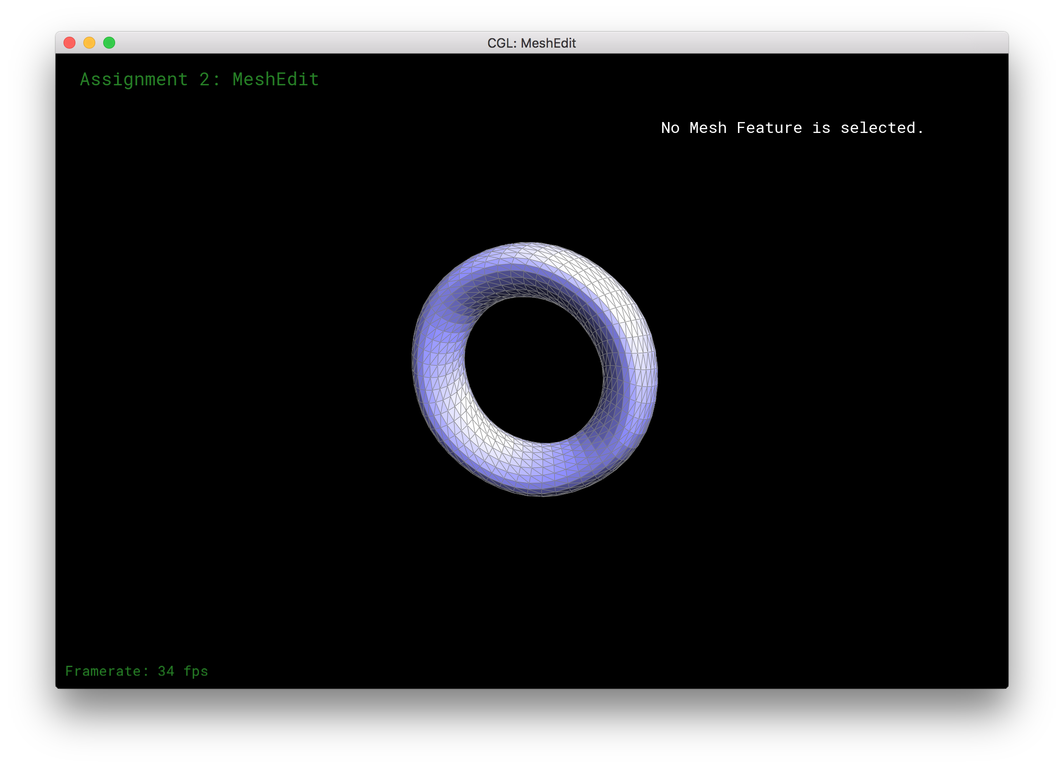
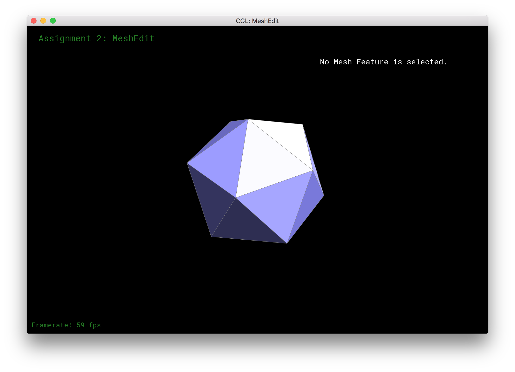
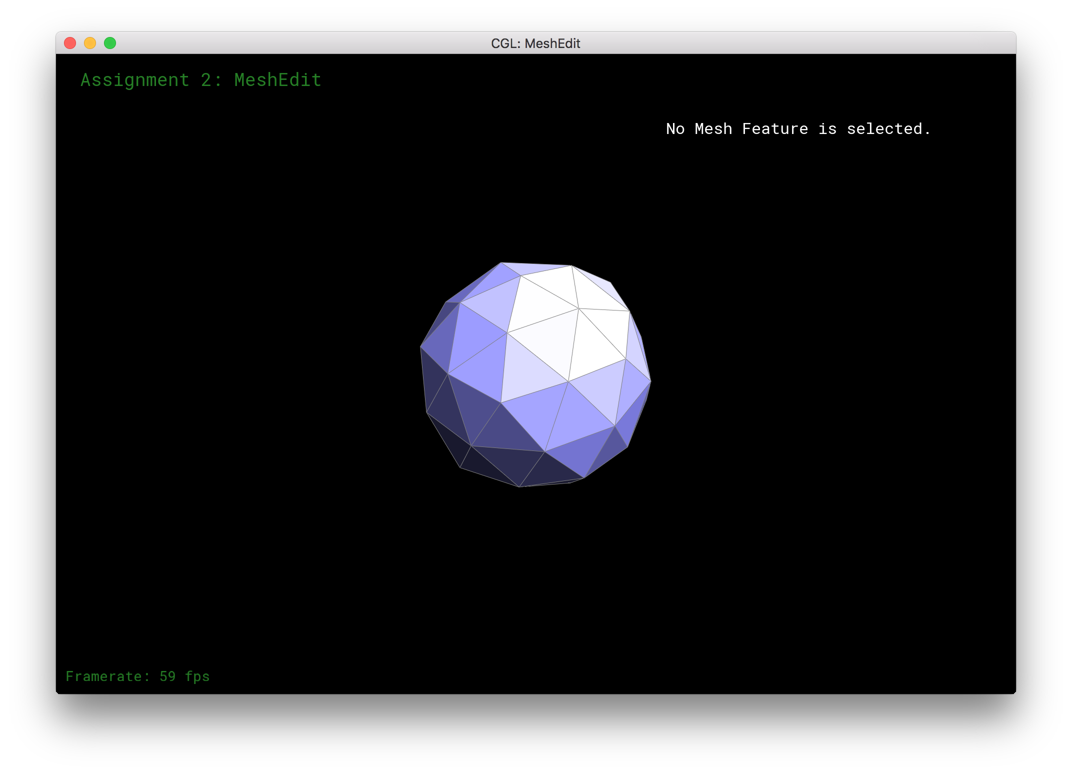
Part 6: Loop subdivision for mesh upsampling
I implemented loop subdivision in a couple of steps that were outlined by the project spec:
First, I computed new vertex positions for all the pre-existing vertices. This involved a weighted averaging scheme based on the number of neighboring vertices for a given vertex and averaging the neighboring vertex locations based on these weights. The scheme also took into account the original position and weighted this more heavily than the neighbor positions.
Next, I computed "midpoints" for all the pre-existing edges. Again, however, a weighted averaging scheme was used which considered both the edge endpoints as well as the neighboring vertices. However the original endpoints were given a higher weight than the neighbor vertices. This step was fairly straightforward.
Then I took every pre-existing edge, and split it. Additionally, I assigned the new vertex the position of the "midpoint" between the edges that I calculated in the previous step.
Finally, I flipped any newly created edge which connected a pre-existing vertex with one that was created by a split. In doing so, we essentially upsample a given mesh, adding points and smoothening sharp edges in the surfaces based on the averaging schemes mentioned above. Below are some of my results for some of the basic meshes.
|
|
|
|
|
|
|

|
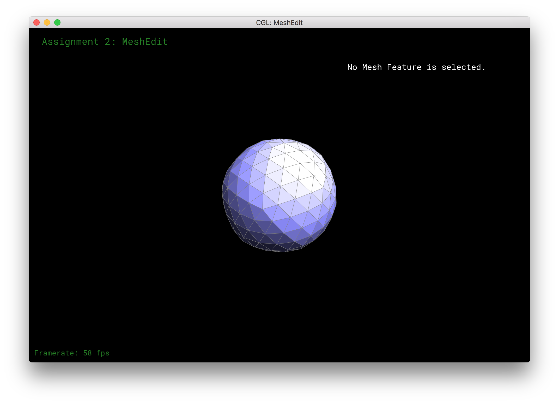
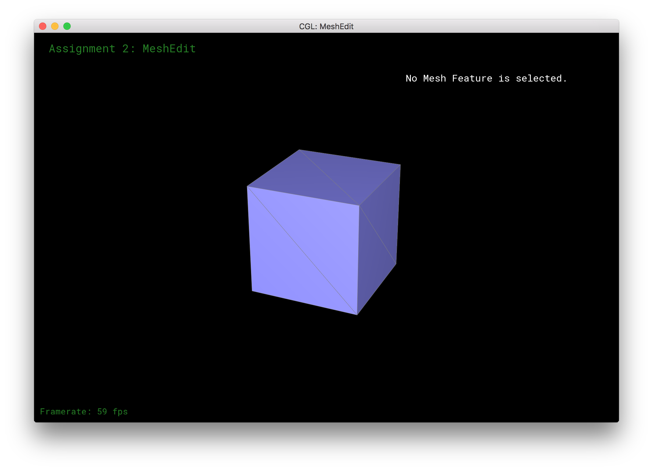
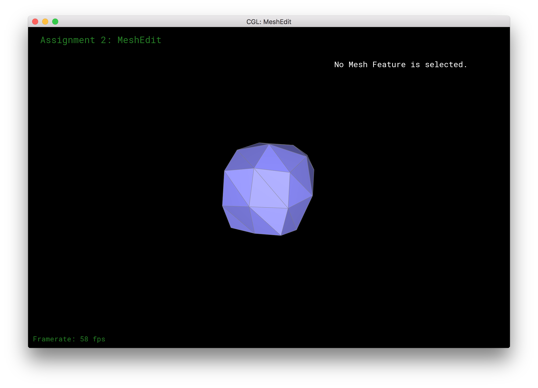
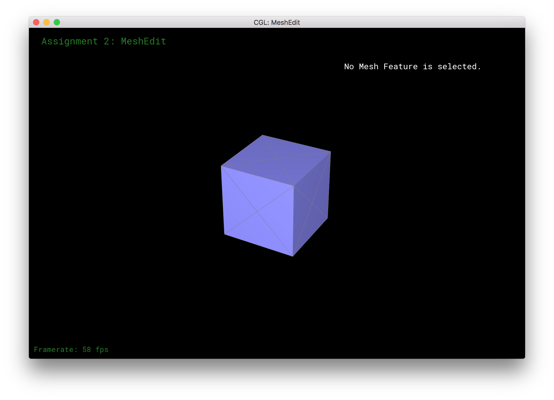
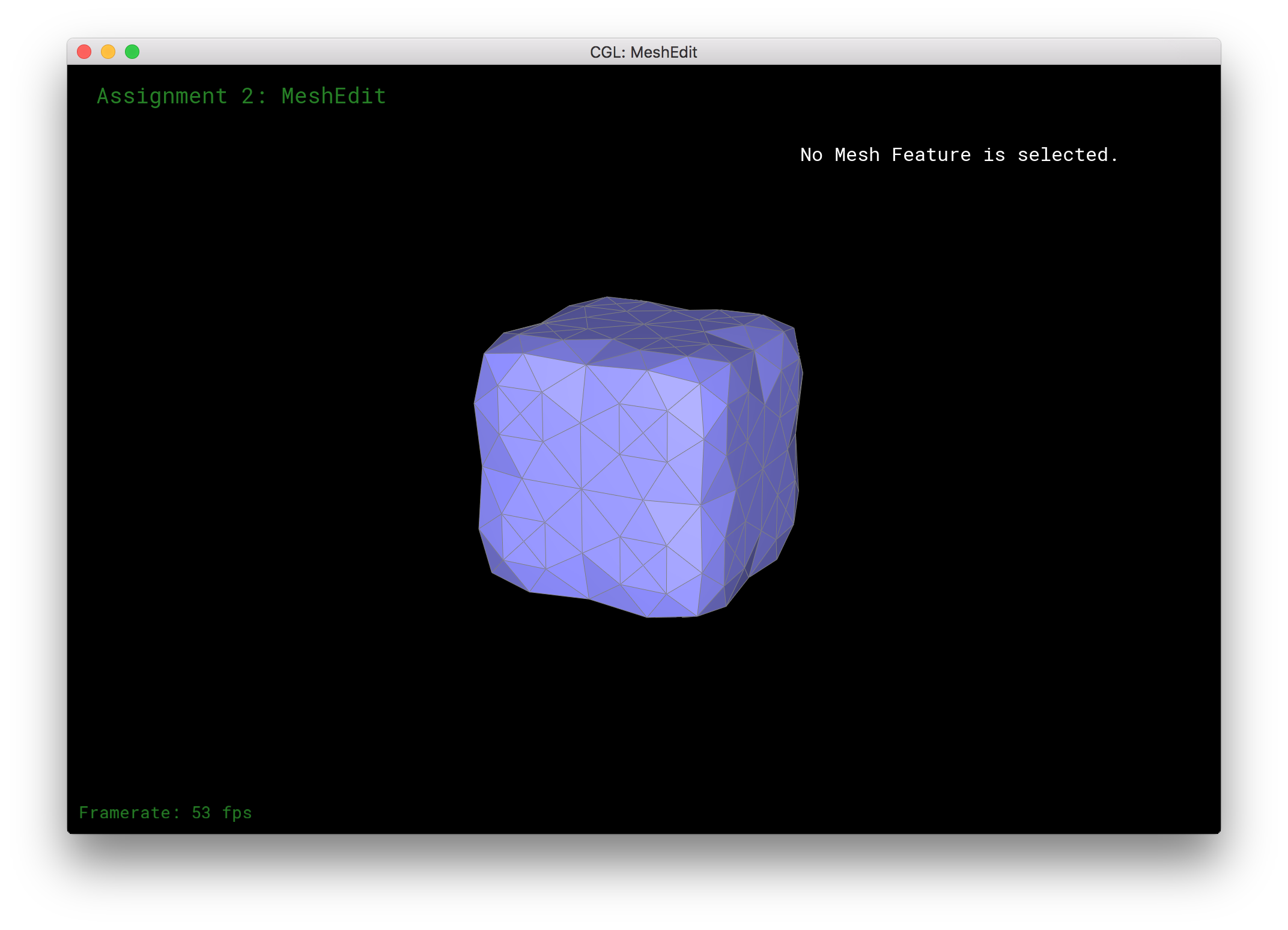
Additionally, I noticed that the cube mesh becomes lopsided as it is upsampled. This is most likely because the mesh itself is not symmetric to begin with as you can see below.
|
|
|
|
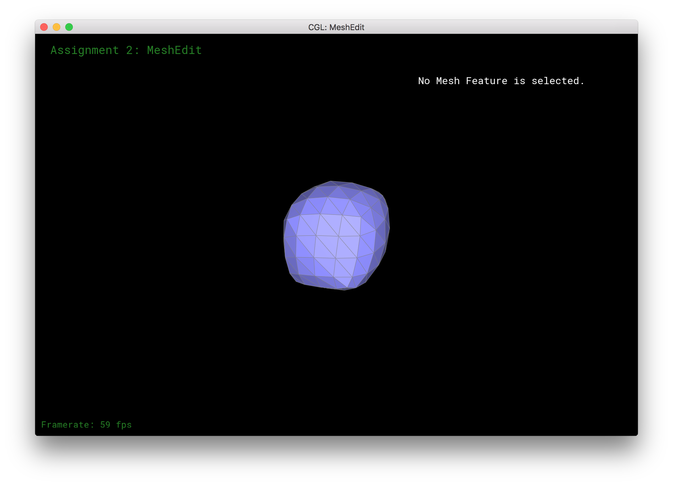
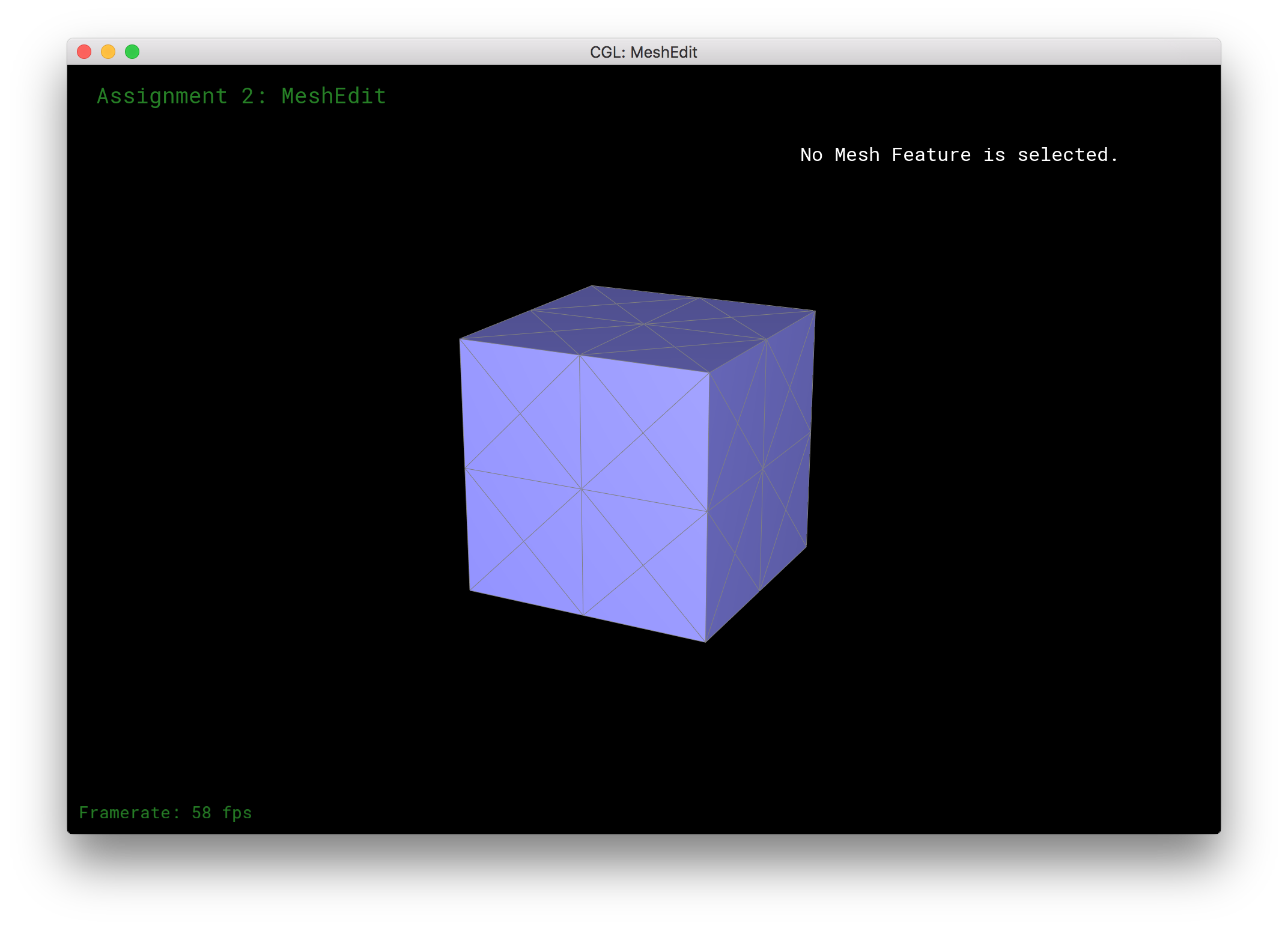
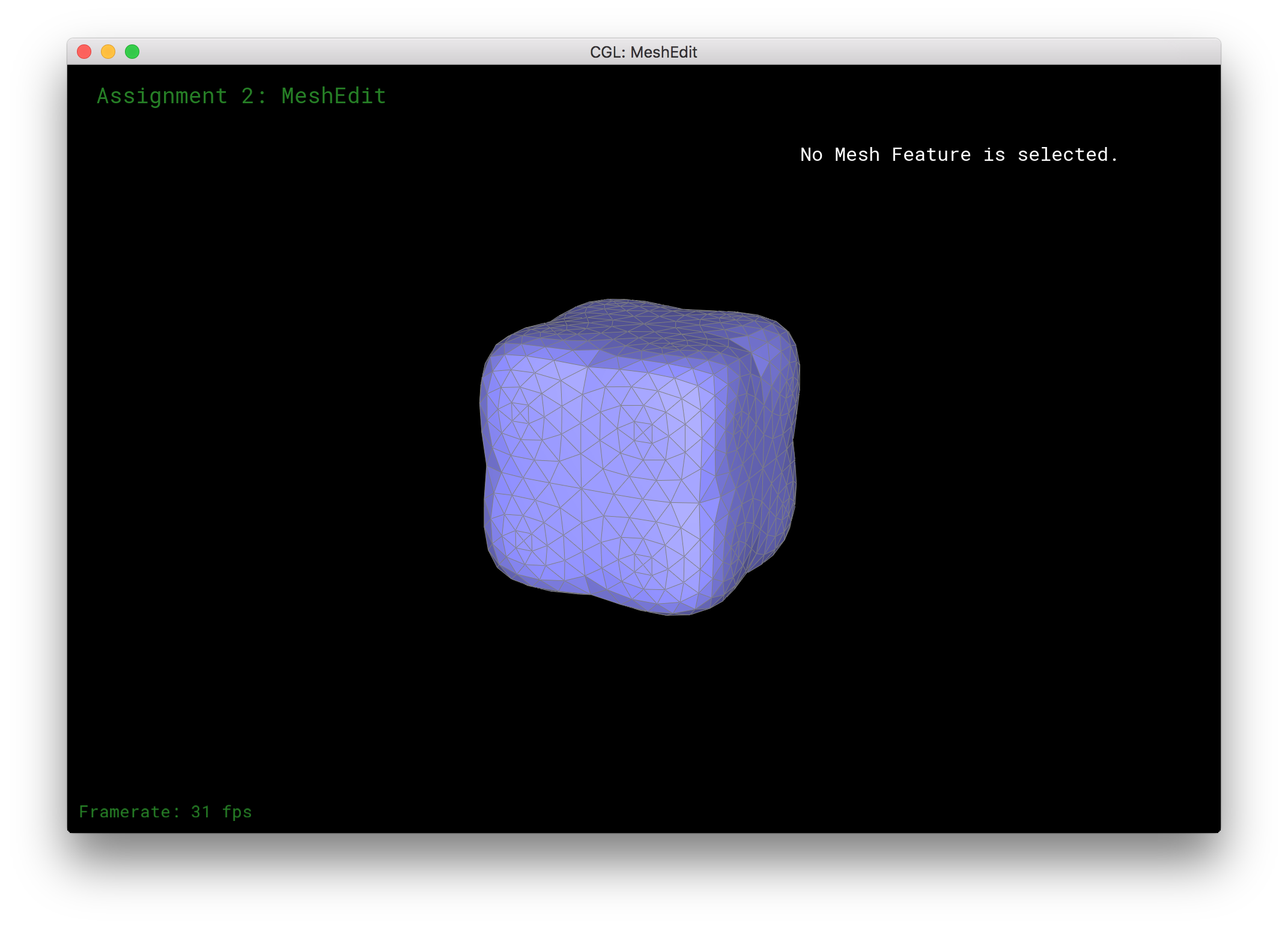
In order to lessen this effect, I pre-split the edges so that they would be symmetric on all faces. I got the following result.
|
|

|

|
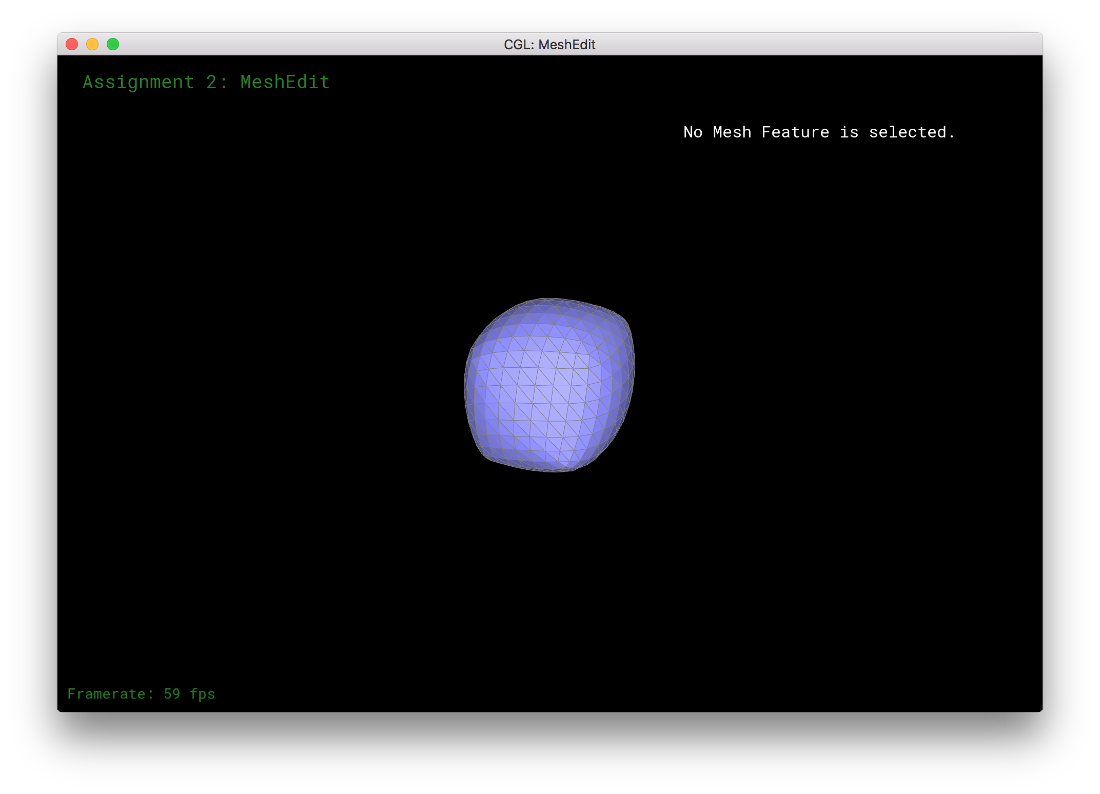
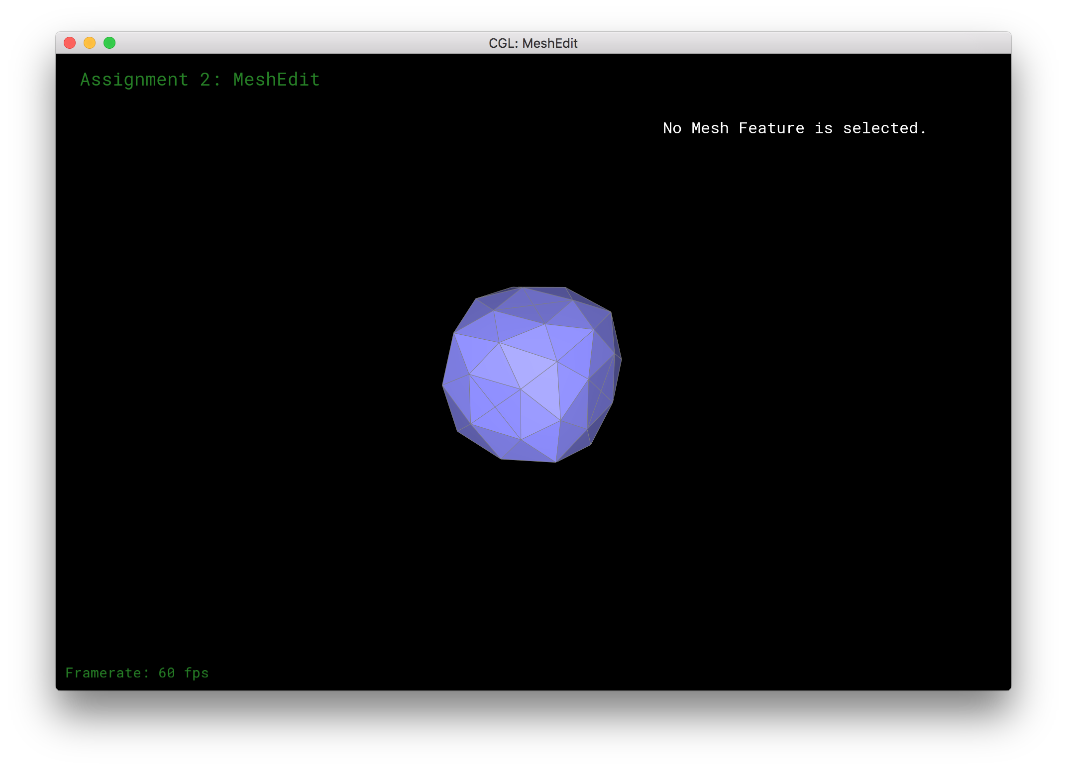
Finally, I also noticed that sharp edges and corners were greatly lessened when upsampling. We see this very clearly in the cube in that it becomes almost elliptical or circular in shape. This makes sense because our original cube is having its vertices and edges averaged to create the new upsampled result. However in order to counter this smoothing while still employing our upsampling algorithm, we can pre-split the edges a lot to retain the shape. In doing so, each edge and vertex contributes less to the overall change in the surface. The results are below.
|
|
|

|
Section III: Shaders
Part 7: Fun with shaders
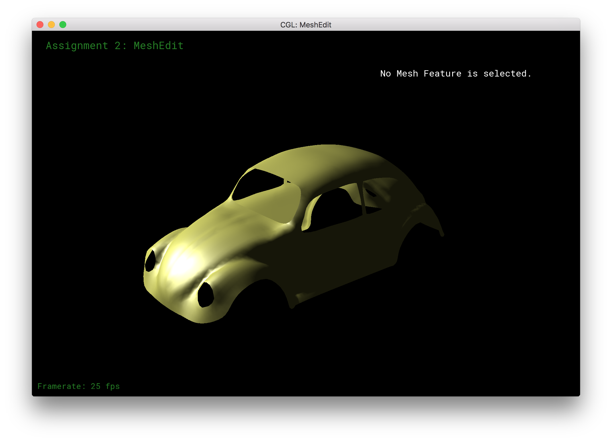
In this part, we implemented the Binn-Phong shading model. This model is interesting because it not only uses an ambient layer for color, it also adds diffuse and specular layers to make the shading of a given mesh more realistic. Below are some examples I ran on our favorite, the teapot mesh, along with some other meshes in the input set.
|
|
|